July 13, 2020
Introduction
I recently moved to a new house that has sprinklers, which is new to me. After fighting with the sprinkler controllers that were previously installed, I decided I wanted to have more control. I started researching how sprinkler controllers and valves work and decided it would be extremely simple to build my own controller using parts I had lying around the house already.Theory & Testing
A sprinkler valve works by applying alternating current across two wires. You can do tests with DC, but they are designed for running on around 24 volts AC. When I was doing my basic experimentation, I determined that I could use my 18V battery pack from my cordless drill to test each valve to verify they worked properly. To make a sprinkler valve work, you just connect both wires to your power supply, and it will turn the valve on. From an automation perspective, it's really, really simple, and the reason why I decided I could easily build my own controller. Check out this video from Rainbird on how the valves work:I've played with relay controllers in the past to turn things off and on from a Raspberry Pi. Mostly it was simple things like lights, but I never had a practical use, so I just had parts lying around. Since turning a sprinkler valve on and off is as simple as applying voltage, it seemed like a perfect project to implement my basic skills. I also don't like hardware control of complicated things, and the sprinkler controllers that were already installed were confusing to get working as expected. I later figured out that there were two controllers and I was messing with the wrong one (but that's neither here nor there!).
I only had four relays on my controller board, but there were six valves to control all of the various lawn sections and flower beds. I manually tested and figured out the water pressure was fine running multiple valves at the same time, so that wasn't going to be a problem. If you need more control, there are larger relay controller boards available and plenty of GPIOs on the Pi to do at least 8 channels, if not more.
Plan
The plan was to write some simple software on the Pi to turn each of the valves on for a pre-determined length of time, and then turn it off. I have six valves, but only four relays on the controller board, so I just need to group some of the valves together into a Zone and run them at the same time. Originally, I planned on writing a web interface to control all of this. After thinking about it, I decided that it didn't make sense to build a web interface; only I would ever need access to this and being the creator I should know how it all works. So the plan was to just have a script scheduled via a cron job on my Raspberry Pi that runs daily to run the sprinklers. This makes it super easy to schedule runs, if I need it to run multiple times or less than once per day, I can easily do that.
Inventory
The items I used to build the controller are as follows:- Raspberry Pi Zero W - The location where the wiring for the sprinkler valves was too far away to run a hard-wired network connection and the Zero W has WiFi built in. This was the only thing I had to buy that I didn't have already sitting around the house. You can do this with any version of the Raspberry Pi. I built the original prototype with a RPi Model B from 2011, and it worked perfectly fine. I didn't even have to reinstall the OS, I just moved the micro SD card from the prototype to the Zero W and it worked out of the box!
- A 5V USB power supply that can run both the Pi and the relay board safely
- Pins to solder on to the Pi Zero, since the WH was not available for purchase when I wanted to buy it
- A JBtek 4-channel relay board, an 8-channel is also available. There are even larger ones, but you may run out of GPIOs if you are using pins for things other than simple I/O.
- Terminal blocks to connect everything easily and make it removable at a later date if necessary
- A 24VAC power supply designed for sprinkler valves (I just disconnected the one from the existing Rainbird controller)
- An inline fuse holder and 3A fuse to make sure nothing burns up
- A box to contain everything. Since this is mounted in the garage, it doesn't need to be water tight or anything fancy. I used an old cassette tape organizer with some thin wood mounted in the bottom with VHB. The link on this page is to one I bought for a future project to control the pool pump remotely.
- Cable glands to protect the wires going in/out of the box
- Wire to connect everything together. Anything will work, as you won't be pulling much current. I just cut off wires from a dead computer power supply.
 Hardware
The hardware is very basic to set up. You just need to wire the Pi to the relay controller per the instruction all over the internet. Find four GPIOs you would like to use on your board and run a jumper wire from each pin on the Pi to the appropriate channel pin on the relay controller. I chose 17, 18, 22 and 23. Connect pin 2 on the Pi to the VCC pin on the relay controller for 5V. Connect pin 6 on the Pi to the GND pin on the relay controller. That covers the low voltage control for the project.

Next we will tackle the higher voltage that can actually run the sprinkler valves efficiently. With AC power, there is no distinction between positive and negative, which makes life easy. We just take one leg of the power, turn it around and run it directly out to the sprinklers. We're using this wire like a ground or common wire, even though it's AC so it's actually hot half the time. Be careful with it, and if possibly just unplug the transformer if you are messing with this part.
Take the other wire coming out of the power supply and run it through a fuse. Since the sprinkler valves are exposed to the elements, if anything happens out there, we don't want the power frying anything inside our controller other than the sacrificial fuse of course. From the fuse, you will pigtail the wire off four ways and connect each separate wire to one of the center terminals on the relay side of the controller board. This is our "output" that we can toggle on and off with the relays. Since they all require the same input voltage, the pigtail makes it easy to do this. Now, take each of the sprinkler valve wires coming from outside and either connect them directly to the left terminal for each relay, or go into a terminal block and connect the terminal block the relay board for a cleaner design.
After that, you should have everything connected up, and be able to do some tests with software.
Code
For this project, I am assuming you have already got a functional operating system running on your Pi. If not, find one of the various tutorials out there on how to load the OS onto your micro SD card and get it booted up. Once you are running and have your Pi on your network, you will need to install the GPIO Zero library for python. If you are running a Debian-based OS, it should be as simple as running apt-get install python-gpiozero.For readability, I split the Zone definition into a separate class file. Below is the code for both files need to get this to run, or you can just download the tar file and extract it on your Pi. Please note that this if the first python code I've ever written, so go easy! I'm more of a C# or bash kind of programmer, depending on the environment. Because of the need to interface directly with hardware (GPIO), this needs to run as the root account (sudo ./sprinklers.py).
#!/usr/bin/python
# sprinklers.py
import datetime
from gpiozero import LED as GPIO
from time import sleep
from sprinkler_classes import Zone


def datestamp():
  return datetime.datetime.now().strftime("%Y-%m-%d %H:%M:%S")


# Zone format = GPIO, duration in minutes, friendly name, description
zones=[
  Zone(23, 15, "Zone 1", "This is the first zone"),
  Zone(22, 15, "Zone 2", "This is the second zone"),
  Zone(18, 10, "Zone 3", "This is the third zone"),
  Zone(17, 10, "Zone 4", "This is the fourth zone")
]


time_between_zones=30


print datestamp(), "\tStarting sprinkler run."


# for each zone, configure the GPIO, start the zone, wait the duration,
# stop the zone, wait a pre-determined amount of time before moving on
# to the next one
for zone in zones:
  print datestamp(), "\tRunning", zone.name, "for", zone.duration, "minutes."
  gpio=GPIO(zone.channel,False);
  gpio.on()
  sleep(zone.duration * 60)
  gpio.off()
  print datestamp(), "\t", zone.name, "run is completed."
  sleep(time_between_zones)


print datestamp(), "\tSprinkler run has completed."
#!/usr/bin/python # sprinkler_classes.pyThe code is pretty self-documenting. It basically loops through the list of configured zones (GPIOs) and toggles each one on for the defined amount of time, then toggles it back off. It's easy to expand this code to handle more than the four zones I have by just adding the new zones to the zone array definition at the top. It will automatically loop through everything in the list in order. You can configure things like the amount of time it waits between each zone run. I found that 30 seconds was a reasonable amount of time to make sure all of the sprinklers settled down to their closed position once it was done running, before moving on to the next zone. This makes sure the pressure is fully available immediately for the next run, and the sprinklers come on strong instead of kind of getting stuck. This may be a local problem to my specific sprinklers? The code outputs everything to standard output. If you want to log it, it's as easy as redirecting to a file.
class Zone: def __init__(self, channel, duration, name, description): self.channel = channel self.duration = duration self.name = name self.description = description
For the actual cron job that runs this on a schedule, it's really basic:
0 6 * * * /root/sprinklers/sprinklers.py >> /var/log/sprinklers.logThis just runs the script daily at 6:00am local time. It logs the output from the script to a file in the /var/log directory. I also have two other cron jobs that email myself the log file every Saturday and then clean it out so it doesn't get too large. I originally had it emailing me every morning, but deemed that too often and moved to a weekly log review.
Update: I wrote a bash script using the sunrise-sunset.org API to schedule my sprinklers to run 30 minutes before sunrise every day, no matter what time that is. It uses curl, date, and an extra library called jq to parse the JSON data that is returned. The extra libraries were installed by typing sudo apt-get install curl jq. Now, instead of running the sprinklers.py script directly in my crontab, I instead run this script at 3am that writes out a file into the /etc/cron.d directory (which are automatically loaded by the cron daemon). So now, it figures out the sunrise for my area, subtracts 30 minutes, and writes that in a cron-compatible line format to the file. I've been monitoring my sprinklers, and they come on a few minutes later each day, as we head into fall here in the northern hemisphere.
#!/bin/bash
cronfile='/etc/cron.d/sunrise'


# Rancho Cucamonga, CA
lat='34.106'
lng='-117.593'


api_url="https://api.sunrise-sunset.org/json?lat=$lat&lng=$lng"


data=$(/usr/bin/curl -s -A 'Sunrise Getter 0.1 Alpha' $api_url)


time=$(echo $data | /usr/bin/jq -r ".results.sunrise")
sunrise_h=$(/bin/date -d "$time UTC" +%H)
sunrise_m=$(/bin/date -d "$time UTC" +%M)


sunrise=$(/bin/date -d "$sunrise_h:$sunrise_m AM" +%H:%M)
start_time_h=$(/bin/date -d "$sunrise_h:$sunrise_m AM -30 minutes" +%H)
start_time_m=$(/bin/date -d "$sunrise_h:$sunrise_m AM -30 minutes" +%M)


#echo "$sunrise  $start_time"


echo '# m  h  dom  mon  dow  user-name  command' > $cronfile
echo "$start_time_m $start_time_h * * * root /root/sprinklers/sprinklers.py >> /var/log/sprinklers.log" >> $cronfile
Results
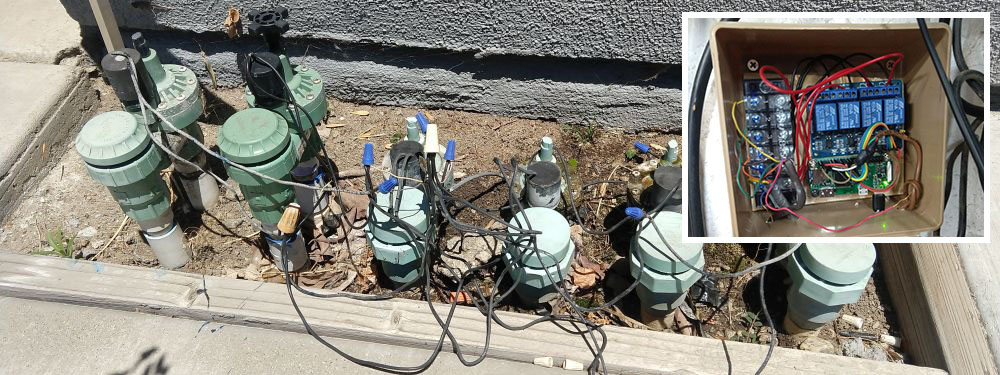
This was a resounding success! My lawn and flowers are being watered every morning and everything is thriving. I have full control over the system by changing a few numbers at the top of the python scripts where the zones are defined. During the summer, I can increase the run time, and during the winter months, I can dial it back to only water every other day. If I know there is going to be a rain storm the next day, I can disable the job for the day. The project is not very conducive to pretty pictures, but here are a couple of the valves and the actual sprinkler controller, prior to cleaning up the messy wiring and installing the fuse. The valves outside
 This is the actual controller. The picture was taken before the cable glands and inline fuse were installed.